This algorithm reconstructs a 3D volume from a set of 2D image slices.
The reconstructor takes as input a set of tracked ultrasound slices. A rectangular or fan-shaped clipping region may be applied on each slice to make sure only valid image regions are used for reconstruction. Angle range of fan-shaped clipping region may be adjusted automatically based on image contents to exclude areas in the image that remain blank because lack of acoustic coupling between the transducer and the scanned surface.
At the beginning of the reconstruction, a 3D voxel array is constructed (location, size, and resolution is specified in the configuration file or detected automatically from the location of the image slices). Then, each pixels of slice is inserted into a volume (distribution step). Each pixel value is inserted either into the spatially nearest single voxel or into the spatially nearest set of 8 voxels according to options specified in the config file.
Once all the available frames have been inserted, an optional hole-filling step may be performed. An algorithm is used to attempt to fill each voxel that has not been assigned any intensity value in the distribution step.
Troubleshooting volume reconstruction
- I got an error from PlusServer when trying to reconstruct a volume: StartReconstruction failed due to out of memory. Try to reduce the size or increase spacing of the output
- This means that you run out of memory space. If you use a 32-bit application then the practically available memory space for image data is approximately 1GB (regardless of how much physical or virtual memory is available), including all inputs, temporary buffers, and output. If 64-bit release is used then the available memory space is practically unlimited (if there is not enough physical memory in the system then the operating system can be configured to use more virtual memory, at the cost of some performance decrease). What can be done:
- Use a 64-bit release. If some devices are only supported in 32-bit releases then run two instances of PlusServer. 1. Acquisition server: 32-bit PlusServer, connects to hardwareacquires devices acquires data, and makes it available through OpenIGTLink (see Acquisition server config file sample at the bottom of the page). 2. Processing server: 64-bit PlusServer, connects to the Acquisition server to receive tracked image data, performs volume reconstruction and other processing, and broadcasts the results to all connected clients (see Processing server configuration file example at the bottom).
- Decrease the resolution of the output by increasing the output volume spacing (
OutputSpacing) - Perform a low-resolution "scout scan" reconstruction from file (e.g., with 3mm spacing), define the region of interest, and then do high-resolution live reconstruction. During live reconstruction the input frames do not have to be kept in memory, which allows reconstruction of higher-resolution volumes. This workflow is implemented in PlusRemote with a nice graphical user interface (available as a 3D Slicer module in the SlicerOpenIGTLink extension)
- Reduce the region of interest size (change
OutputExtent,OutputSpacing, andOutputOrigin)
- I got an error: Path not found from Image to Reference ... / Failed to get transform ... from transform repository
- You have to specify the transform that is applied to each frame to insert them into the volume. It is typically a transform from the image coordinate system to a reference coordinate system (such as a reference sensor or the tracker). Usually the sequence files contain transforms between the tracker and the probe coordinate frame, which is not directly usable for the reconstruction, because the coordinate frame of the image and the probe is not the same. Therefore the configuration file should contain the image to probe transform (typically computed by free-hand probe calibration).
- You can get the Path not found error if there is no transforms defined between the specified image and reference coordinate frames. Either the image or the reference coordinate frame name does not match the coordinate frame names described in the input sequence file. Or, no image to probe transform matrix is defined in the configuration file.
- Check the slice positions using the CrateSliceModels tool
- Image orientation (MF/MN/UF/UN) does not influence the slice locations, only the image contents within the slice. Therefore if the slice locations are not correct (do not seem to correspond to the actual motion of the transducer) then most likely the ImageToProbe matrix is not correct.
- Check the ImageToProbe matrix
- You can use fcal to display your image plane, models, coordinate system axes in real-time which can help you to understand why/how the transform is not correct. See the Frequently asked questions page for more details.
- Check the image orientation
- First make sure that the slice positions are correct. You cannot verify the slice orientations if their position is incorrect.
- Acquire a 3D volume single sweep of a pencil. Move the probe along a straight line with one abrupt shift (left/right or up/down).
- Reconstruct the volume. If the image orientation is correct then the reconstructed volume should show a smooth surface (there should not be a break in the surface).
Configuration settings
- VolumeReconstruction

- ReferenceCoordinateFrame Defines the Reference coordinate system name: the volume will be reconstructed in this coordinate system (the volume axes are parallel to the Reference coordinate system axes and the volume origin position is defined in the Reference coordinate system). If not defined then the coordinate system name has to be specified by other means before starting a reconstruction.

 Default =
" " - ImageCoordinateFrame Defines the image coordinate system name: it corresponds to the 2D frame of the image data in the tracked frame. If not defined then the coordinate system name has to be specified by other means before starting a reconstruction.
Default =
" " - OutputSpacing Output image resolution for each dimension of the reconstructed volume. Vector of 3 numbers, separated by spaces.

- OutputOrigin Is output image origin position vector for each dimension of the reconstructed volume. Vector of 3 numbers, separated by spaces.
Default =
"0 0 0" - OutputExtent Defines the size of the reconstructed volume. Vector of 6 numbers (x start, x end, y start, y end, z start, z end), separated by spaces. Usually the start values are 0, end values are the intended size - 1.
Default =
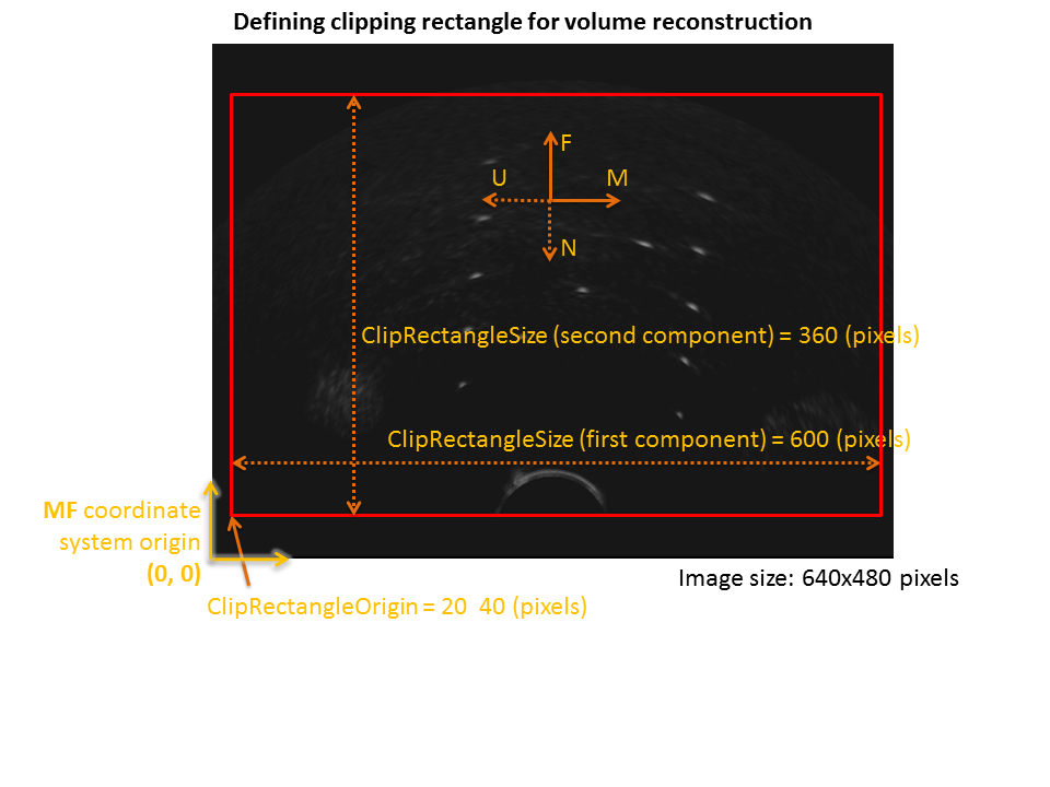
" " - ClipRectangleOrigin Crop rectangle origin of the frame (in pixels). See more information in the Clipping section.
Default =
"0 0" - ClipRectangleSize Crop rectangle size of the frame (in pixels). If it is
"0 0"then the whole frame will be captured. See more information in the Clipping section.
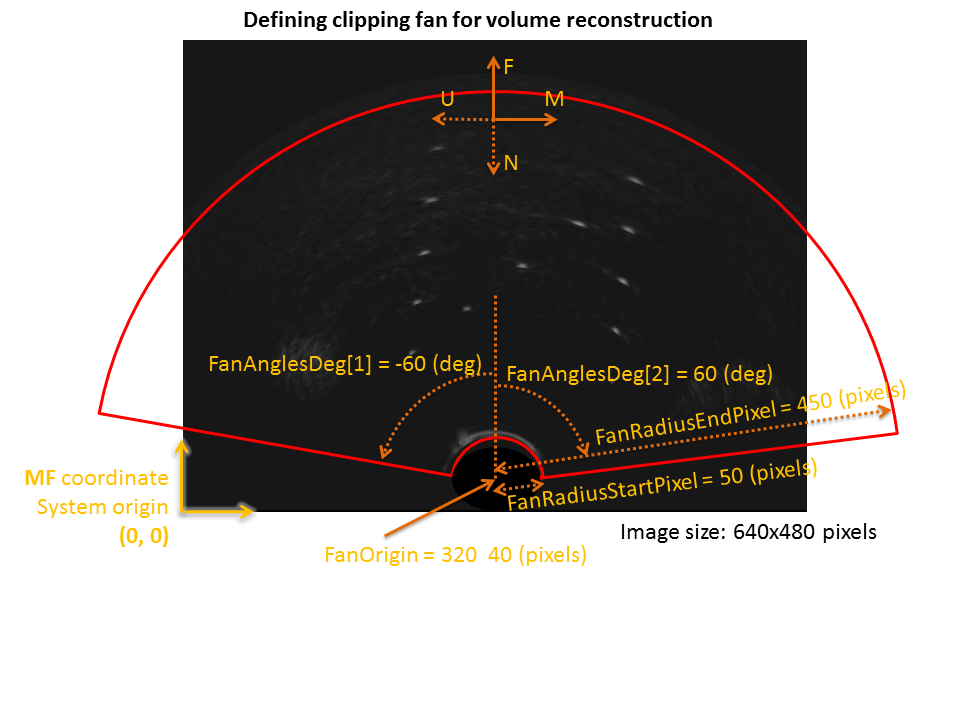
Default ="0 0" - FanAnglesDeg Two-element vector containing the angles of the two straight edge of the fan, in degrees. If both angles are 0 then no fan clipping is performed. See more information in the Clipping section.
Default =
"0 0" - EnableFanAnglesAutoDetect If enabled then the provided fan angle is used as maximum limit for the angle range and the actual start and stop angle is determined fro each frame automatically, based on the image contents. This switch is useful for excluding shaded black areas from the image reconstruction (e.g., those parts that remained black because there was insufficient acoustic coupling between the skin surface and the transducer).
TRUEorFALSE.
Default ="FALSE" - FanAnglesAutoDetectBrightnessThreshold Fan angle range where all pixels remain below this threshold will be discarded if fan angle auto-detection is enabled.
Default =
"30" - FanAnglesAutoDetectFilterRadiusPixel Radius of the filter that is applied to detect non-blank fan angle ranges (in pixels). If the radius is larger then larger continuous regions will be detected.
Default =
"10" - FanOriginPixel Two-element vector containing the origin of the clipping fan, in the image coordinate system (in pixels). See more information in the Clipping section.
Default =
"0 0" - FanRadiusStartPixel Minimum depth of the clipping fan in the image coordinate system (in pixels). See more information in the Clipping section.
Default =
"0" - FanRadiusStopPixel Maximum depth of the clipping fan in the image coordinate system (in pixels). See more information in the Clipping section.
Default =
"500" - PixelRejectionThreshold Pixels that have lower brightness value than this threshold value will not be inserted into the volume. If not specified then all pixels in the clipping rectangle/fan will be pasted into the output volume. Higher values remove more of the dark image regions therefore reducing the chance of the striping artifact but it removes dark image areas everywhere. Typically a few levels above the completely black value works well (for example, for an image in the 0-255 range, a value of 3 may work).
Default =
" " - SkipInterval only every [SkipInterval] images from the input will be used in the reconstruction (i.e., this is the number of frames that are skipped when the index is increased)
Default =
"1" - Interpolation Set the interpolation mode
Default =
"NEAREST_NEIGHBOR"NEAREST_NEIGHBOREach pixel is inserted only into the spatially nereast voxel. Faster, but is susceptible to noise. (default)LINEAREach pixel is distributed into the surrounding eight voxels using trilinear interpolation weights. Resists noise, but is slower and may introduce blurring.
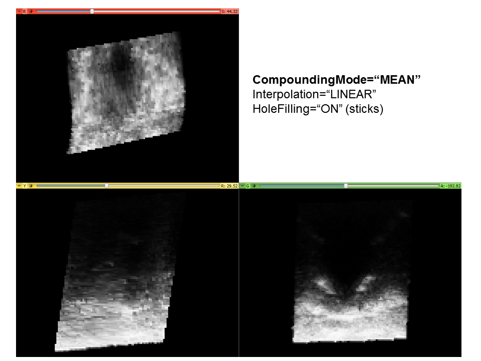
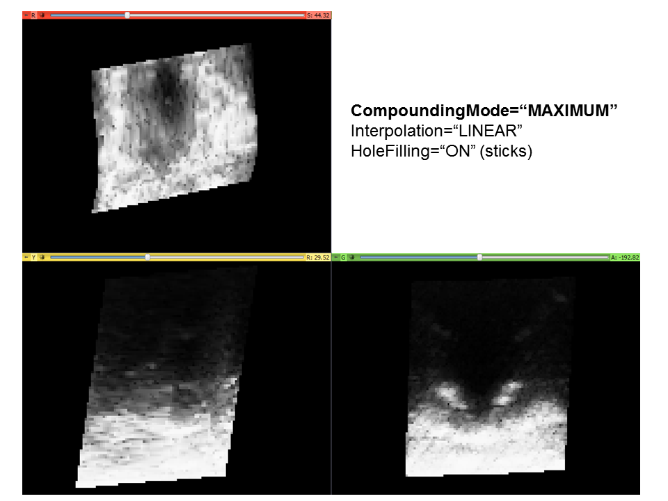
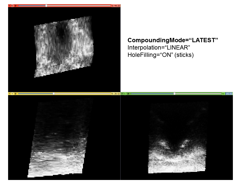
- CompoundingMode Set the method for compounding overlapping input pixels. See examples of the effect of compounding mode in Compounding mode section.
Default =
"MEAN"MEANFor each voxel, use an average of all inserted pixel values. Used on single or multiple sweeps from the same angle (regardless of intersection). Resistant to noise, but slower than other compounding methods.LATESTFor each voxel, use only the latest inserted pixel value. Used on single or multiple sweeps from the same angle (regardless of intersection). Fast, but susceptible to noise.MAXIMUMFor each voxel, use only the pixel value with the highest intensity. Used when multiple slices from different angles are expected to intersect. Fast, but susceptible to noise.
- Optimization Set optimization method (turn off optimization only if it is not stable on your architecture).
Default =
"FULL_OPTIMIZATION"NONEMeans no optimization (almost never used).PARTIALBreak transformation into x, y and z components, and don't do bounds checking for nearest-neighbor interpolation.FULLFixed-point (i.e. integer) math is used instead of float math, it is only useful with NEAREST_NEIGHBOR interpolation (when used with LINEAR interpolation then it is slower than NO_OPTIMIZATION).
- NumberOfThreads Set number of threads used for processing the data. The reconstruction result is slightly different if more than one thread is used because due to interpolation and rounding errors is influenced by the order the pixels are processed. Choose 0 (this is the default) for maximum speed, in this case the default number of used threads equals the number of processors. Choose 1 for reproducible results.
Default =
"0" - FillHoles If enabled then the hole filling will be applied on output reconstructed volume.
ONorOFF.
Default ="OFF" - HoleFilling:
If FillHoles
="ON"- HoleFillingElement The user can specify one or more hole filling "elements" which are tried one by one until either one succeeds or they all fail. If the hole is not filled (all methods fail), then the hole remains a black voxel with value 0.
- Type There are currently five types of hole filling elements, each with several parameters that can be set, one Type and its respective attributes is required:
GAUSSIANThe hole is filled using a gaussian-weighted average over a surrounding cubic neighborhood.GAUSSIAN_ACCUMULATIONSame asGAUSSIANbut it uses the accumulation buffers as a weighting factor.STICKThe hole is filled by looking along several directions through the hole and interpolating between pairs of opposite voxels:NEAREST_NEIGHBORA small 3 x 3 x 3 cube-shaped kernel is placed over the hole. If there are any filled voxels in the region, then a simple mean of filled voxels is used to fill the hole voxel. If not, then a slightly larger kernel size (eg, 5 x 5 x 5) is used, until a maximum kernel size (as defined by the user) is reached.DISTANCE_WEIGHT_INVERSEIt is weigthed inversly proportional to the euclidian distance of each pixels.
- Size An odd integer representing the diameter of the largest possible kernel for hole filling. A larger region will be more likely to encompass more information for the interpolation, but it will increase the running time.
If Type
="GAUSSIAN", Type="GAUSSIAN_ACCUMULATION", Type="GAUSSIANNEAREST_NEIGHBOR", or Type="DISTANCE_WEIGHT_INVERSE" - MinimumKnownVoxelsRatio A floating point number between 0 and 1 indicating the ratio of voxels in the neighborhood that must be known in order to fill the hole (ie, 0.5 means that 50% of voxels in the cubic region must be known, or the hole will not be filled).
If Type
="GAUSSIAN", Type="GAUSSIAN_ACCUMULATION", Type="GAUSSIANNEAREST_NEIGHBOR", or Type="DISTANCE_WEIGHT_INVERSE" - Stdev a floating point number representing the standard deviation of the Gaussian weight.
If Type
="GAUSSIAN"or Type="GAUSSIAN_ACCUMULATION" - StickLengthLimit An integer representing the maximum length of the stick used to fill the hole. A smaller value means that the algorithm will take longer, but that suitable values are more likely to be found.
If Type
="STICK" - NumberOfSticksToUse An integer representing the number of sticks that should be used in calculating the final voxel value. The voxel will be calculated as a weighted average of individual stick results. The results of these sticks will be weighted according to their length.
If Type
="STICK"
Clipping
Images slices often contain irrelevant parts for volume reconstruction, e.g., dark or black regions at the image boundary or out of the image fan. To remove these image regions a rectangular and fan-shaped clipping areas can be defined.
Clipping rectangle must be always defined. Clipping fan is optional and it is applied in addition to the clipping rectangle: all pixels that are outside the clipping rectangle or outisde the clipping fan will be ignored in volume reconstruction.
Clipping rectangle and clipping fan are always defined in the MF coordinate system. If the UltrasoundImageOrientation field in the stored sequence file is not MF and the file is loaded into a generic software that ignores the UltrasoundImageOrientation field (such as ImageJ, 3D Slicer, Paraview) then the XY positions and orientations shown in the generic software has to be transformed. For example, if the image size is 640x480 pixels and UltrasoundImageOrientation=MN and the FanOrigin appears in the (320,440) position in ImageJ then the FanOriginPixel in the XML config file shall be (320,40).
Compounding mode
Examples
Example configuration file PlusDeviceSet_Server_Sim_NwirePhantom.xml
Example configuration file PlusDeviceSet_VolumeReconstructionOnly_SonixRP_TRUS_D70mm_NN_LATE.xml
Example configuration file PlusDeviceSet_VolumeReconstructionOnly_SpinePhantom_NN_MAXI.xml
Example configuration file for Acquisition server (PlusDeviceSet_Server_Sim_NwirePhantomTrackedFrameAcquisition.xml)
Example configuration file for Processing server (PlusDeviceSet_Server_Sim_NwirePhantomTrackedFrameProcessing.xml)