Coordinate system definitions used by fCal
Coordinate systems used in fCal:
| Reference frame name | Origin | Unit | Axes directions |
|---|---|---|---|
| Phantom | fCal-2.x and fCal-3.x phantoms: inside end of the A5 hole on the front (see picture). | mm | X axis: from column A to B direction Y axis: towards the back side of the phantom Z axis: from row 4 to row 1 direction |
| Reference | Origin of the marker that is attached to the calibration phantom | mm | as defined by the tracking system / marker manufacturer |
| TransducerOrigin | Position of the pixel that is in the middle of the first line of the MF oriented image. In PLUS it's only used for approximate visualization of the transducer 3D model. | mm | Same as Image |
| TransducerOriginPixel | Same as TransducerOrigin | pixel | Same as TransdrucerOrigin |
| Tracker | see common coordinate systems description | - | - |
| Stylus | see common coordinate systems description | - | - |
| Probe | see common coordinate systems description | - | - |
| StylusTip | see common coordinate systems description | - | - |
| Image | see common coordinate systems description | - | - |
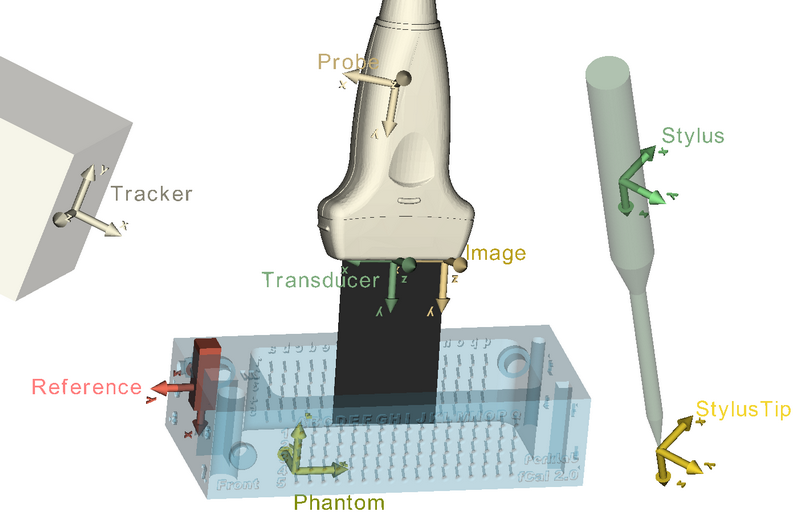
Coordinate systems overview sketch (3D Slicer compatible interactive 3D model of the figure below is available here):