Motivation
The acquired ultrasound image orientation (which direction is left/right, which direction is towards the probe) depends on a number of factors, such as settings on the ultrasound device (horizontal, vertical flip), transducer type, and image acquisition hardware/software settings. When a transducer is calibrated (the image to probe transform is determined), the calibration is valid for one particular image orientation, therefore it is important to be able to exactly identify the current image orientation.
Plus defines the image orientation using a two or three letter acronym, the first and second letter specify the transducer principal axes directions corresponding to the +x and +y directions in the image coordinate system, respectively. The third letter is only defined for three-dimensional probes and represents the +z direction in the image coordinate system.
Transducer axes definition
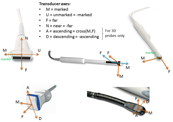
The following transducer principal axes directions are defined:
- Marked (M): lateral transducer axis, pointing towards the marked side of the transducer (from the center of the crystal array).
- Unmarked (U): lateral transducer axis, pointing towards the unmarked side of the transducer (from the center of the crystal array).
- Far (F): axial transducer axis (normal to the transducer surface), pointing away from the transducer (towards increasing depth direction).
- Near (N): axial transducer axis (normal to the transducer surface), pointing towards the transducer.
- Ascending (A): elevational transducer axis, cross product of M and F axis (so that MFA forms a right-handed 3D coordinate system), only for 3D probes
- Descending (D): elevational transducer axis, opposite to A direction, only for 3D probes
Directions for commonly used transducer types:
Definition of ultrasound image orientation
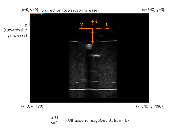
The ultrasound image axes are defined as follows:
- x axis: points towards the x coordinate increase direction
- y axis: points towards the y coordinate increase direction
In B-mode images typically each scanline displayed approximately vertically (x = near constant, y = 0..n). In RF-mode images each scanline is stored in a 'row' (x = 0..n, y = constant).
The image orientation can be defined by specifying which transducer axis corresponds to the x and y image axes, respectively.
There are four possible orientations for 2D B-mode images:
- MF: image x axis = marked transducer axis, image y axis = far transducer axis
- MN: image x axis = marked transducer axis, image y axis = near transducer axis
- UF: image x axis = unmarked transducer axis, image y axis = far transducer axis
- UN: image x axis = unmarked transducer axis, image y axis = near transducer axis
There are four possible orientations for RF-mode images:
- FM: image x axis = far transducer axis, image y axis = marked transducer axis
- NM: image x axis = near transducer axis, image y axis = marked transducer axis
- FU: image x axis = far transducer axis, image y axis = unmarked transducer axis
- NU: image x axis = near transducer axis, image y axis = unmarked transducer axis
There are eight possible orientations for 3D B-mode images:
- MFA
- MNA
- UFA
- UNA
- MFD
- MND
- UFD
- UND
Image orientation in Plus
Plus always uses MF image orientation internally for 2D B-mode images and MFA for 3D B-mode images and FM orientation for 2D RF-mode images. Plus performs any required flipping operations between M<->U, F<->N, A<->D when importing images from the imaging device (based on the PortUsImageOrientation attribute of the Device element in the device set configuration file).
Transposing operation (conversion between M<->N, F<->U, etc.) is not performed automatically, because this conversion typically requires scan conversion instead of a simple reordering of the pixels, that is why orientations for B-mode and RF-mode images are different.
Example
The image x axis points towards the same direction as the U (unmarked) transducer axis. The image y axis points towards the same direction as the F (far) transducer axis. Therefore, the ultrasound image orientation is: UF.
How to check that the UsImageOrientation attribute is set correctly:
- Start fCal application
- Go to the "Freehand calibration" tab
- Click on the "Show segmentation parameter editing dialog" button (icon)
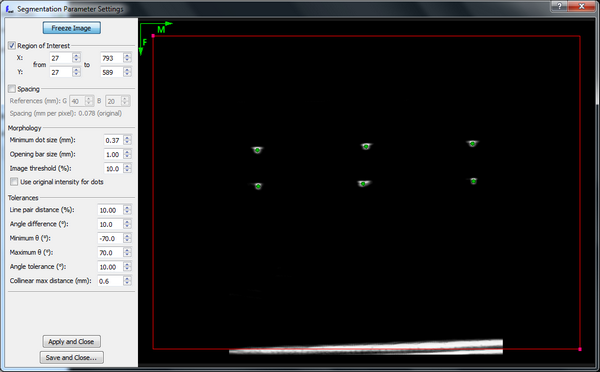
- In the window the M and F directions are shown with arrows (M points to the right, F points downwards)
- If the UsImageOrientation is set correctly, then
- The transducer surface shall appear at the top of the image
- If you touch the marked side of the transducer surface then the finger shall appear on the right side of the image
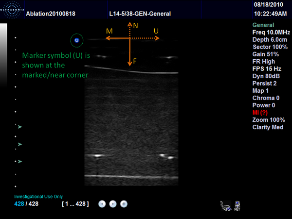
Image orientation in the Ultrasonix software
The Ultrasonix software shows an image orientation marker (blue "U" symbol) at the marked / near corner of the image.