Definition of commonly used coordinate systems
In Plus the following coordinate systems are used commonly:
| Reference frame name | Origin | Unit | Axes directions |
|---|---|---|---|
| Tracker | Origin of the tracking system (position of the field generator, camera, etc.) | mm | as defined by the tracking system manufacturer |
| Stylus | Origin of the marker that is attached to the pointer tool | mm | as defined by the tracking system / marker manufacturer |
| Probe | Origin of the marker that is attached to the ultrasound probe (transducer) | mm | as defined by the tracking system / marker manufacturer |
| Reference | Origin of the marker attached to the object of interest (phantom, cadaver, patient, etc.) | mm | as defined by the tracking system / marker manufacturer |
| StylusTip | Tip of the stylus | mm | X axis: aligned with the Stylus coordinate system's X axis (unless StylusTip Z axis is parallel with the StylusTip Z axis - in this case the StylusTip Y axis is aligned with the Stylus X axis). Y axis: chosen to be the cross product of the Z and X axes. Z axis: the axis that points from the Stylus coordinate system origin towards StylusTip coordinate syste origin. |
| Image | Position of the pixel that is in the origin of the MF oriented image | pixel | X axis: towards the marked side of the transducer Y axis: towards the direction that points away (far) from the transducer Z axis: cross product of X and Y |
| Transducer | Center of the transducer crystal array | mm | X axis: towards the marked side of the transducer Y axis: towards the direction that points away (far) from the transducer Z axis: cross product of X and Y |
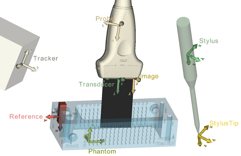
Coordinate systems overview sketch (3D Slicer compatible interactive 3D model of the figure below is available here):